ACT / Research & patents
The tests
behind the systems.
Nothing here is a claim. Every figure on this page comes from a full-scale specimen that was built, instrumented, loaded until it failed, and published. The curves below are redrawn from that measured data — press Run again on any of them to replay the loading from zero.
Applied Mechanics 7(2), 2026 — article 49
External RC knee joints
reinforced with a rebar truss
Four full-scale specimens, each with an 1800 mm beam and an 1800 mm column, were loaded to failure under a closing moment. Three used conventional detailing — the main tension bars bent around the corner — and one used the ACT truss reinforcement system, two parallel trusses with simple mechanical joints and both a diagonal tension and a diagonal compression member crossing inside the knee.
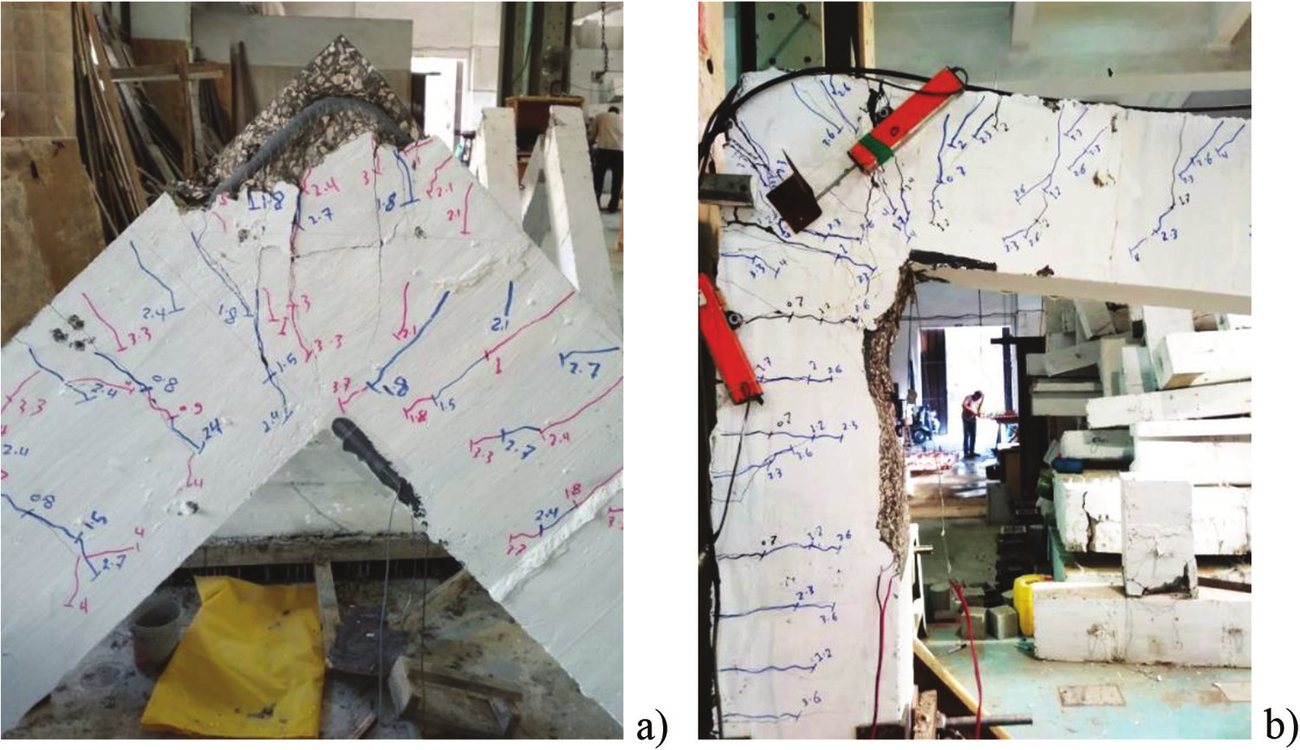
The three conventional specimens all failed in the joint. The truss specimen did not: cracking in the knee was effectively eliminated, the failure moved out into the mid-span of the column, and loading was stopped at 51 kN and 180 mm because the concrete at the support had started to crush — not because the specimen had failed.
| Specimen | fcu | Py | Pu | Δu | µΔ | Failure |
|---|---|---|---|---|---|---|
| R1 conventional | 34 MPa | 26.09 kN | 28.08 kN | 53.1 mm | 1.09 | Brittle |
| R2 joint stirrups | 34 MPa | — | 28.41 kN | 40.2 mm | — | Brittle |
| R3 conventional | 55 MPa | 34.36 kN | 41.95 kN | 95.7 mm | 2.02 | Semi-brittle |
| TR — ACT truss | 45 MPa | 44.50 kN | 51.01 kN | 180 mm | 5.25 | Highly ductile |
Yield load, ultimate load, displacement at ultimate load and displacement ductility index.
What the strain gauges saw
The tension went somewhere else.
A gauge on the main tension bar (S1) and a second one on the diagonal tension bar of the truss specimen (S2) show why the joint survived. At 50 kN the two gauges in the truss specimen read 1600 and 1200 microstrain — the tensile demand had been shared between the main bar and the diagonal, and the main bar never reached yield.
The conventional specimens did the opposite. R3 was at 3484 microstrain, past the yield line, at only 41.95 kN; R1 and R2 reached the onset of yield at lower loads still. All the tension was concentrated in one bent bar.
And what the concrete felt
The steel skeleton took the load.
The third gauge sat on the concrete surface at the inner corner of the joint, where the diagonal compression strut lands. In the conventional specimen with joint stirrups, that strain shot to about 2800 microstrain at only 28 kN — within touching distance of the 3000 microstrain crushing limit.
The truss specimen, at nearly double the load, never went past 650. The rigid truss skeleton was absorbing the internal forces, and the surrounding concrete was doing a different job — confining the truss members and stopping them buckling. That is the whole idea of the system in one measurement.
Analysis
Predicted, then measured.
A strut-and-tie model was built for the conventional specimens and a simplified truss-based finite element model for the ACT specimen. The predicted failure loads and the measured ones agree closely — which is what makes the system designable rather than merely promising.
| Specimen | Measured Pu | CTT node | Diagonal strut | Horizontal & vertical struts | Governing mode |
|---|---|---|---|---|---|
| R1 | 28.08 kN | 26.85 kN | 19.0 kN | 67.2 kN | CTT node, at the bend |
| R2 | 28.41 kN | 26.85 kN | 23.7 kN | 67.2 kN | CTT node, at the bend |
| R3 | 41.95 kN | 42.20 kN | 19.0 kN | 67.2 kN | CTT node, at the bend |
| TR — ACT truss | 51.01 kN | 86.5 kN | 98.8 kN | 95.0 kN | Column mid-span — not the joint |
For the ACT specimen the joint capacities are far above the load that actually stopped the test. The knee had stopped being the weak point; the members either side of it now govern.
6.38P → 2.8P
Force on the bent main reinforcement, once the diagonal tension member takes its share.
9.02P → 4P
Compressive force in the corner, reduced by the hybrid strut of diagonal rebar plus concrete.
No help
Horizontal and vertical stirrups inside the knee did not raise the diagonal strut capacity — they are not aligned with it.
ACI Structural Journal 118(2), 2021, 153–166
Closing knee joints using
an L-shaped coupler
instead of bending bars
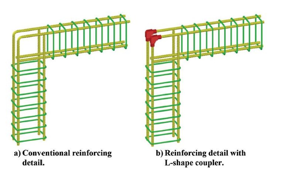
The bend itself is the problem. To turn a beam bar into a column bar, the steel is bent around the corner — and the tensile force running through that curve pushes outwards on the concrete inside it. The cover splits, the corner opens, and the joint fails before the beam or the column has delivered what it was designed for. Bending also work-hardens the bar exactly where the demand is highest.
This programme removed the bend. The main tension bars arrive straight and are joined at the corner by a mechanical L-shaped coupler, so the reinforcement turns the corner through a machined connection rather than through a curve in the steel.
Full-scale specimens were tested under a closing moment against conventionally detailed references. The coupled joints carried more load, deflected further before failing, and stayed stiffer through the loading history. Joint efficiency — the ratio of what the joint delivered to what the members either side of it could deliver — reached 170%, against 144.5% for the bent-bar detail.
Structures 78, 2025, article 109224
Simple mechanical truss joints
in hybrid truss–concrete beams
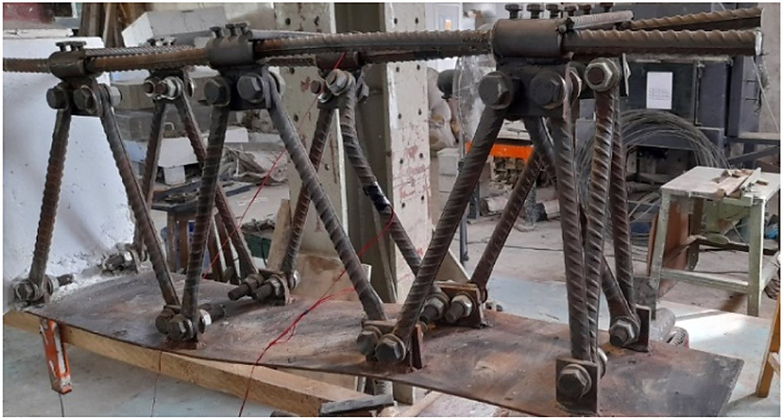
Replace the reinforcement cage of a beam with a steel truss skeleton and two things change. The beam becomes stiff enough to carry its own weight and the weight of the fresh concrete, so the formwork and the propping under it are no longer needed. And the internal forces travel through a rigid triangulated frame instead of through the concrete alone.
The question this programme answered is how to make the truss nodes. Welding a node burns the bar and leaves a brittle heat-affected zone precisely where the force concentrates. So the nodes here are simple mechanical joints — bolted, demountable, and made without touching the metallurgy of the bar.
Specimens were tested under bending against conventionally reinforced references. The mechanically jointed trusses developed their capacity without any joint slip governing the result: the beams behaved as a composite of truss and concrete, with higher stiffness and a gradual, ductile failure rather than a sudden one.
- Self-supporting during casting — formwork and props removed from the programme
- No welding at the nodes, so no heat-affected zone in the reinforcement
- Shop-assembled, delivered as a unit, placed by crane
- The same joint element is used in the knee-joint truss system above
Publications
The full list.
Journal papers
- External RC knee joints reinforced with a rebar truss system under closing moments — Applied Mechanics 7(2), 2026, article 49
- Effect of utilizing simple mechanical truss joints on the performance of hybrid truss–concrete beams subjected to bending — Structures 78, 2025, article 109224
- Behavior of closing knee joints using an L-shaped coupler instead of bending bars — ACI Structural Journal 118(2), 2021, 153–166
- Freshly compressed concrete with natural and artificial fibres — Mansoura Engineering Journal, 2007, C.27–C.36
- Analysis and immediate treatment of concrete column loss and loss of soil support under structures — Mansoura Engineering Journal, 2007, C.1–C.11
- Retrofitting of concrete columns using the mechanical strengthening technique — study cases — Journal of EERM, Al-Azhar University, 2007
- Generalized form of the elastoplastic constitutive matrix — Journal of Engineering and Applied Science, Cairo University, 45(4), 1998, 481–496
- Finite element analysis of slopes — Journal of Soil Mechanics and Foundations, Egyptian Geotechnical Society, 9, 1998, 64–73
- Finite element analysis of c–φ slopes — Journal of Soil Mechanics and Foundations, Egyptian Geotechnical Society, 13, 2001
Conference papers
- Retrofitting of RC beams using active external pressure — 6th Alexandria International Conference on Structural and Geotechnical Engineering, 2007, 295–315
- Types of structural damage sustained in Lebanon in the 2006 conflict — 6th Alexandria International Conference, 2007, 325–340
- Retrofitting of RC columns with accessible and inaccessible faces using the mechanical strengthening technique — 10th Arab Structural Engineering Conference, Kuwait, 2006, 589–600
- Mechanical reinforcing bar coupler based on bar deformations — 10th Arab Structural Engineering Conference, Kuwait, 2006, 297–304
- Strengthening of masonry walls subjected to in-plane and out-of-plane loads — 10th Arab Structural Engineering Conference, 2006, 601–610
- Behavior of retrofitted RC beams using active external pressure — CCC2003, Composites in Construction, University of Calabria, Italy, 2003, 471–476
- Retrofit of reinforced concrete columns using global lateral external pressure — CCC2003, Composites in Construction, University of Calabria, Italy, 2003, paper 186
- Strengthening of concrete beams using the mechanical strengthening technique — 8th International Conference on Inspection, Appraisal and Maintenance of Structures, University of Nottingham, 2001
- An innovative technique for strengthening reinforced concrete elements using mechanical external prestressing — Arab Structural Engineering Conference, 2000, 761–775
- Effect of steel arrangement on the behaviour of RC columns — Arab Structural Engineering Conference, 2000, 805–815
- An effective technique for strengthening structural elements leading to optimum use of materials and cost — Arab Building Materials and Future Challenges Conference, 2000, 57–68
- Neural networks: a solution for the factor of safety problem in slopes — International Symposium on Landslides 2000, Cardiff, Wales, 44–49
- Suggested technique for strengthening reinforced concrete columns subjected to dynamic loads — Arab Conference for Repair and Strengthening of Structures, 1998, 559–571
Thesis
- Numerical procedures for nonlinear static and dynamic analysis of geomaterials and concrete — PhD thesis, Ehime University, Japan, 1996
Reprints of any of the above are available on request.
Want the full papers?
We will send the published test programmes, the specimen drawings and the analytical models.