ACT Advanced Construction Technologies Email us

ACT  /  ACT Systems

Five systems.
Every one tested
to failure.

Reinforced concrete fails at its connections — where a bar is bent, lapped or welded, and where a member is asked to carry more than it was detailed for. These five systems each remove one of those weak points. All are patented, all are published, and all are available for licensing.

Strengthening Karma Truss beams Joints Coupler

System 01 — MST

Strengthening
by confinement

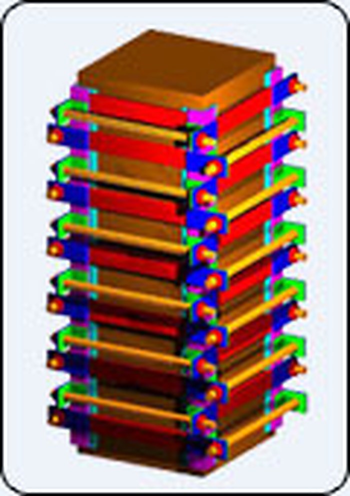
Active external confining pressure is applied along the length of a column or beam through steel angles and plates, then locked in permanently by welded strips. The member gains strength and ductility without gaining size or weight, and without the concrete section being cut into.

  • Columns — axial capacity measured at 212% of the unstrengthened reference, applied while the column was still carrying its working load
  • Beams and connections — higher stiffness and ultimate capacity, delayed cracking, narrower cracks
  • Two, three or four accessible faces — a column against a wall is still a candidate
  • No setting time; the pressure casing moves to the next element the same day

The full technique

US 6,718,723 EG 21,647 EG 23,111 CA 2,325,706

Rectangular column confined by steel angles and horizontal strips, shown in three stages.
Compression through the casing, strips welded, casing removed.

System 02 — Karma

Karma walls
and slabs

A light, low-cost structural system for walls and floors: precast panels made of a lightweight core between two thin layers of reinforced concrete or cement mortar, each with a light reinforcing mesh. The longitudinal rib reinforcement projects beyond the panel so that, on site, ribs of cast concrete tie the panels together and transfer load between wall, slab and floor.

  • Light enough that foundations become very small — buildable on weak soil without deep or large foundations
  • Good sound and thermal insulation
  • Good wind and seismic resistance; stiff, with no sag under added load
  • Cheap, and quick to erect
  • Precast quality control on the concrete, with electrical and plumbing runs cast in
  • No skilled multi-trade labour and no timber or steel formwork needed on site

EG application 2009101449

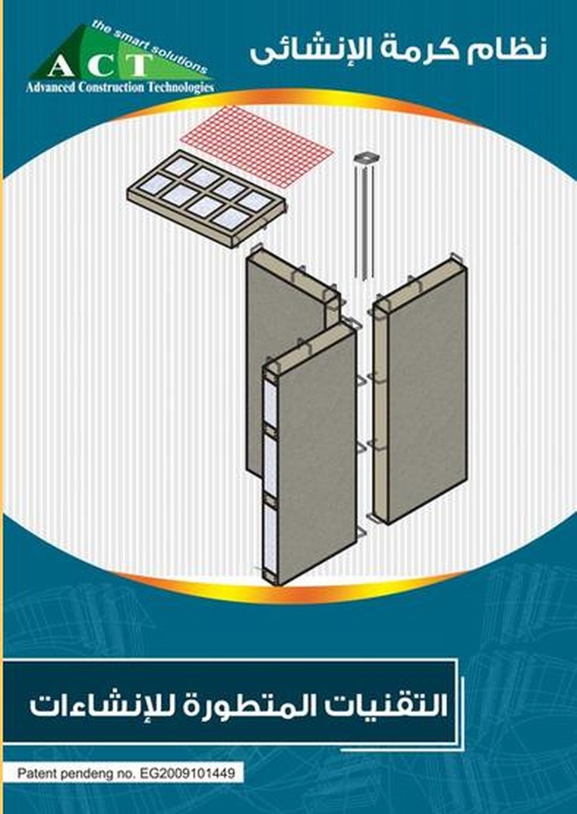
Exploded isometric of the Karma system: two ribbed panels, a lightweight core, connecting reinforcement and a mesh.
Panels, core, tie reinforcement and mesh — assembled on site, tied by cast ribs.

Karma slabs

The modified hollow core slab

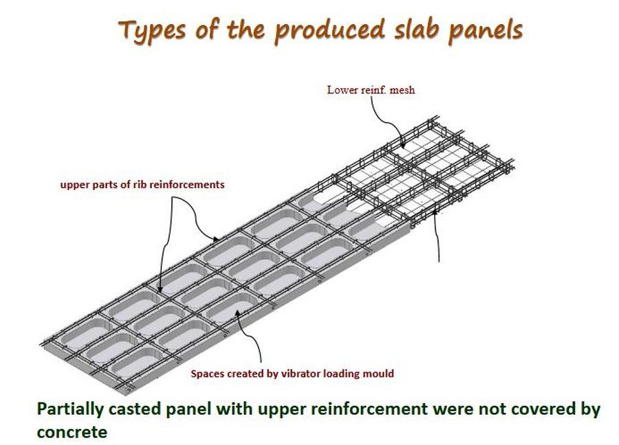
The floor version of the system. Panels are cast in a mould where a vibrating loading head forms rows of voids through the section, so the slab loses most of its dead weight but keeps a full grid of ribs. The panel leaves the yard partially cast: the lower mesh and the lower part of the ribs are in concrete, the upper part of the rib reinforcement is deliberately left exposed.

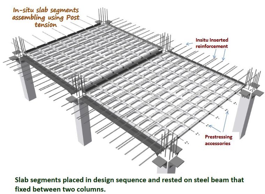
On site the segments are placed in their design sequence, resting on a steel beam fixed between two columns, and further reinforcement is inserted in situ. The exposed rib steel, the inserted bars and the topping are then cast together, and the segments are stressed to one another with post-tensioning tendons. What was a set of light precast pieces becomes one monolithic, prestressed floor plate.

  • Voids formed by the vibrator loading mould — far less concrete and far less dead load per square metre
  • Partially cast panels, so the upper rib steel bonds into the in-situ pour instead of a cold joint
  • Segments rest on a steel beam spanning between columns — no propping across the floor
  • Post-tensioned in plane, in both the slabs and the wall panels
  • Hollow blocks in the wall panels can be filled with lightweight brick or covered by a precast face
Isometric of a produced slab panel: lower reinforcement mesh, upper parts of the rib reinforcement left exposed, and the voids created by the vibrator loading mould.
Partially cast panel — the upper rib reinforcement is left out of the concrete on purpose.
Slab segments placed in design sequence on a steel beam fixed between two columns, with in-situ inserted reinforcement and prestressing accessories.
Segments in design sequence on the steel beam, then assembled by post-tensioning.
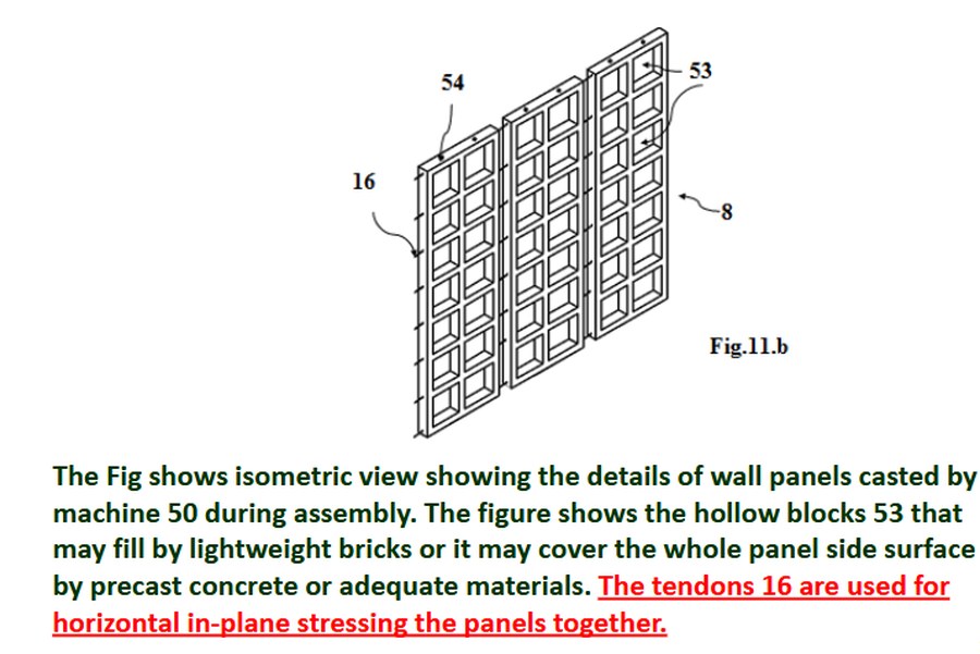
Isometric of wall panels showing the hollow blocks and the tendons used for horizontal in-plane stressing.
Wall panels: hollow blocks, and tendons stressing the panels together in plane.

System 03 — hybrid truss beams

Beams that carry
their own wet concrete

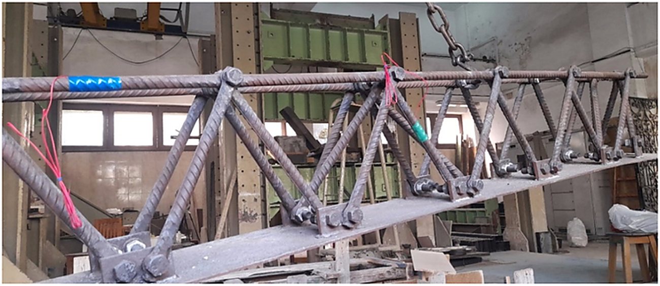
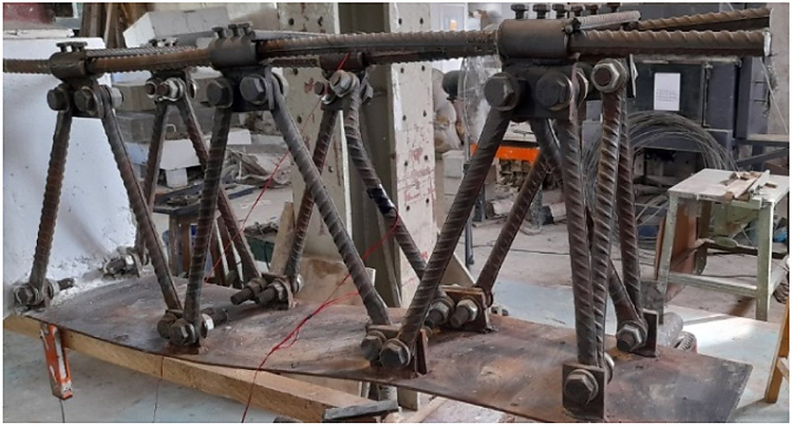
A steel truss skeleton with simple mechanical joints replaces the reinforcement cage of a beam. Because the truss is a structure in its own right, it carries its own weight and the weight of the fresh concrete during casting — so the formwork and the propping under it can go.

The joints are bolted, not welded. Welding a truss node burns the bar and leaves a brittle heat-affected zone exactly where the force concentrates; a mechanical joint does not touch the metallurgy of the bar.

  • Self-supporting during casting — no formwork, no props
  • Assembled in the shop, delivered as a unit, placed by crane
  • Forces distributed through a rigid skeleton instead of through the concrete alone
  • Tested under bending and published in Structures, 2025

See the test programme

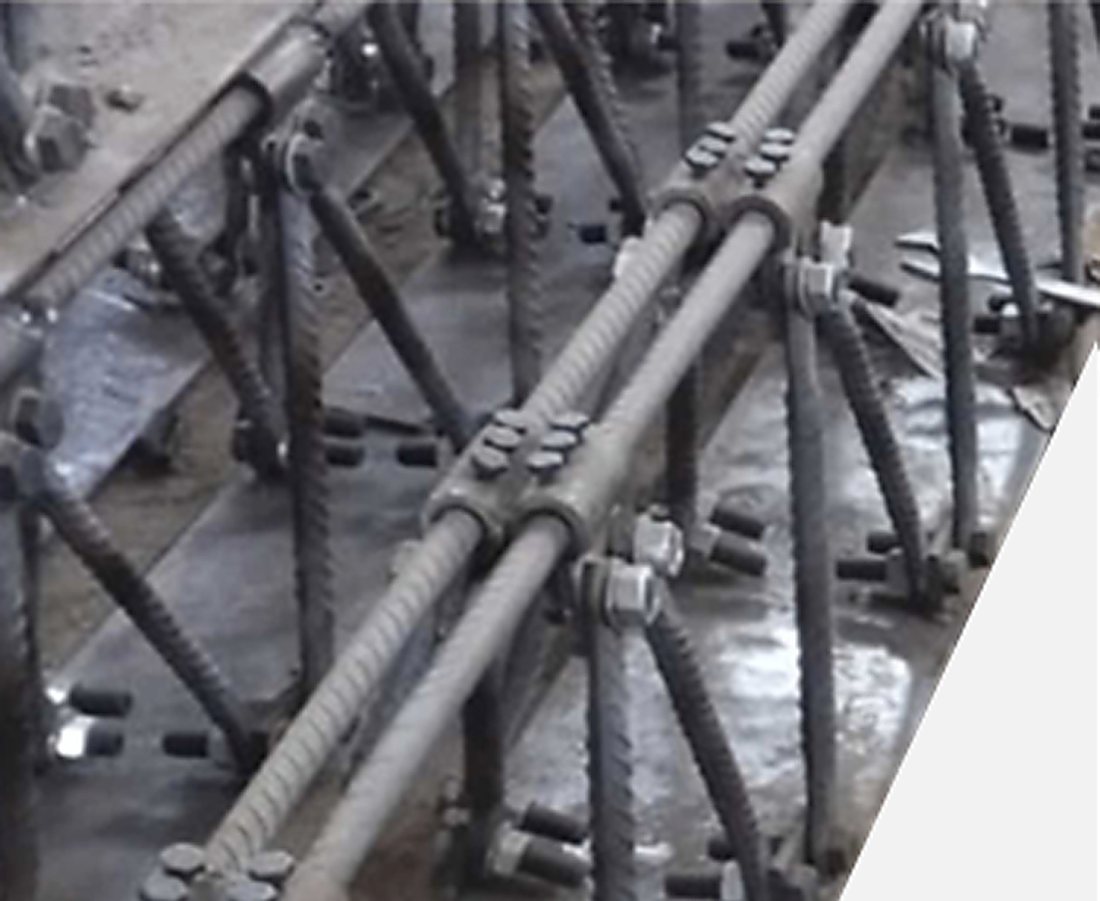
Rebar truss, type A, with bolted mechanical joints.
Rebar truss, type B.
Full truss assembled and ready for casting.

Two joint types; the assembled truss before casting.

System 04 — beam–column joints

Two ways to get rid
of the bent bar.

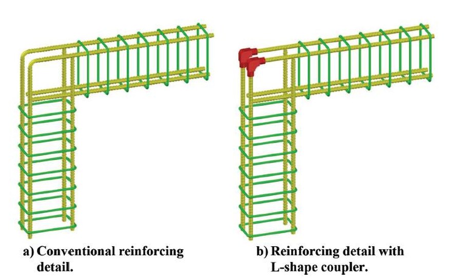
In a frame corner, the main tension bars are bent around the joint. The tensile force pushing through that bend produces radial compression, the concrete cover splits, and the joint fails in a brittle way — long before the members either side of it have given what they are capable of.

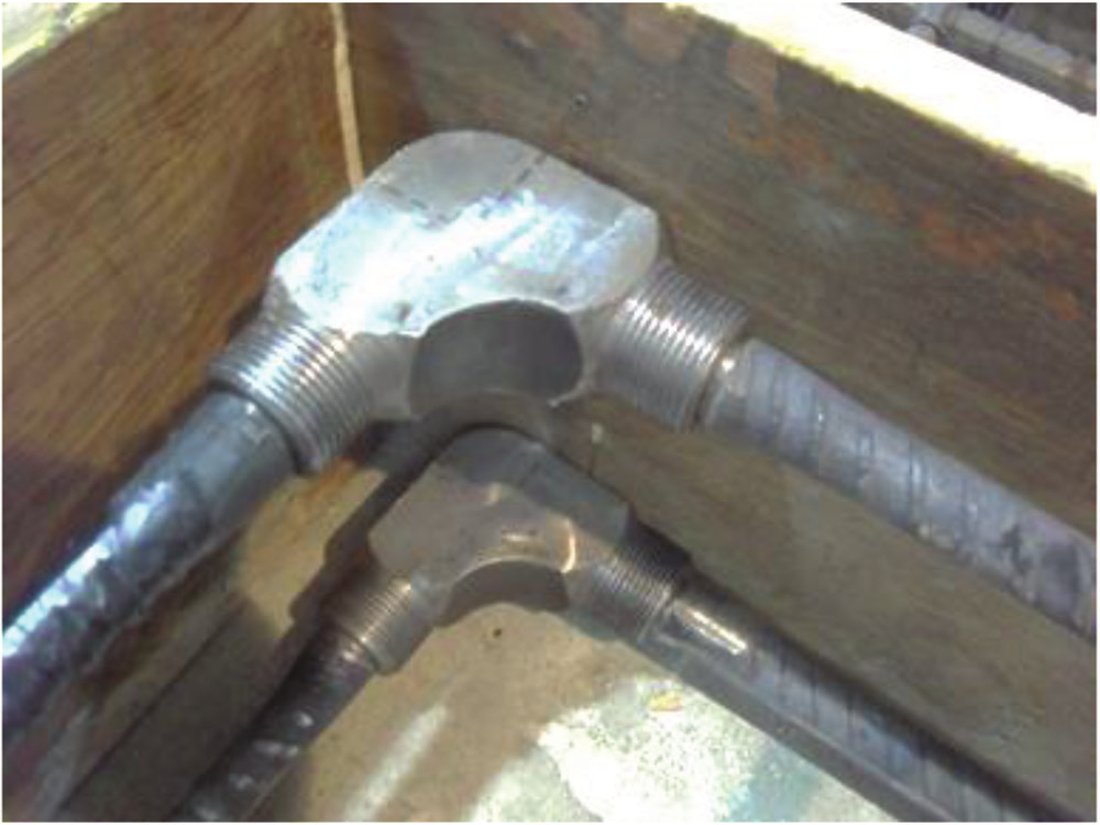
Two reinforcement cages side by side: conventional detailing with bent bars, and the same corner detailed with an L-shape coupler.
a) Conventional reinforcing detail.   b) Reinforcing detail with the L-shape coupler.
The L-shaped mechanical coupler itself.

The L-shaped coupler

The bend is replaced by a mechanical L-coupler. The bar arrives straight, is coupled at the corner, and never gets work-hardened. Ductility, stiffness and load capacity all rise, and joint efficiency goes to 170% against 144.5% for the bent-bar reference.

ACI Structural Journal 118(2), 2021.

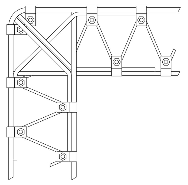
Line drawing of the rebar truss system through a knee joint, with bolted mechanical joints at every node.
The truss carried through beam, knee and column — every node a bolted mechanical joint.
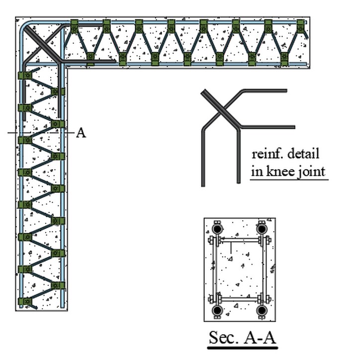
Reinforcement detail of the knee joint with section A-A through the member.
Reinforcement detail in the knee joint, with section A–A.
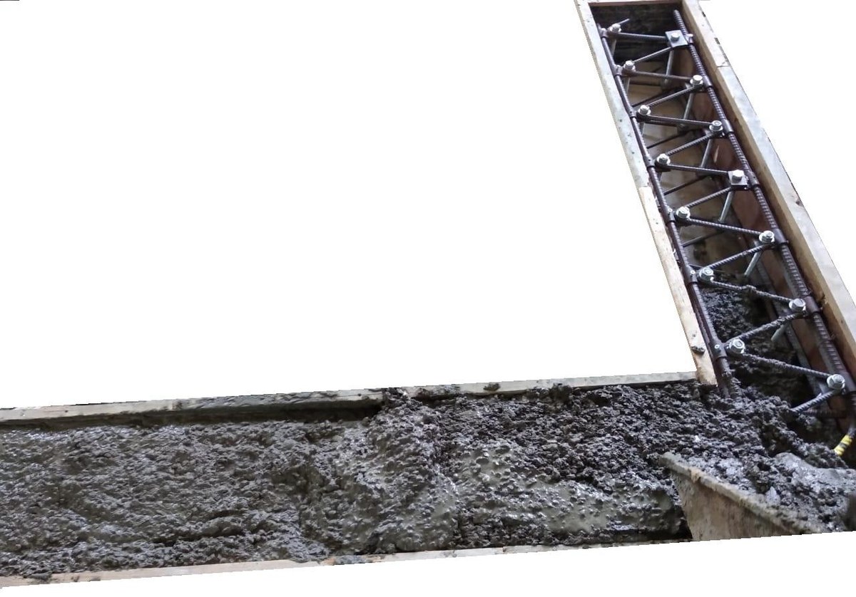
The rebar truss in the formwork of a knee joint specimen during casting.
The truss in the formwork during casting of a test specimen.

The truss reinforcement system

Two parallel trusses run through the beam, the joint and the column, with diagonal tension and compression members crossing inside the corner. The force on the bent main bar drops from 6.38P to 2.8P, the diagonal strut force from 9.02P to 4P, and the failure moves out of the joint into the column.

Applied Mechanics 7(2), 2026, article 49.

+81%Ultimate load of the truss-reinforced knee joint against conventional detailing
+347%Displacement capacity at ultimate load
+126%Stiffness, against the conventional specimen of the same detailing

System 05 — mechanical coupler

The bar broke.
The coupler didn’t.

Reinforcing bars carry outward circumferential ribs. Those ribs are what makes a mechanical coupler difficult: they cut down the contact surface available to transfer load between the bar and the inside of the sleeve, so most couplers end up long, heavy and expensive.

The ACT coupler works on the double action of screw elements. The sleeve is machined with female grooves that interlock with the bar ribs, and screw elements tighten against the bar without threading, enlarging or undercutting it. As the screws bite, the bar ribs are pressed into direct contact with the inner surface of the sleeve and the spaces between them are eliminated.

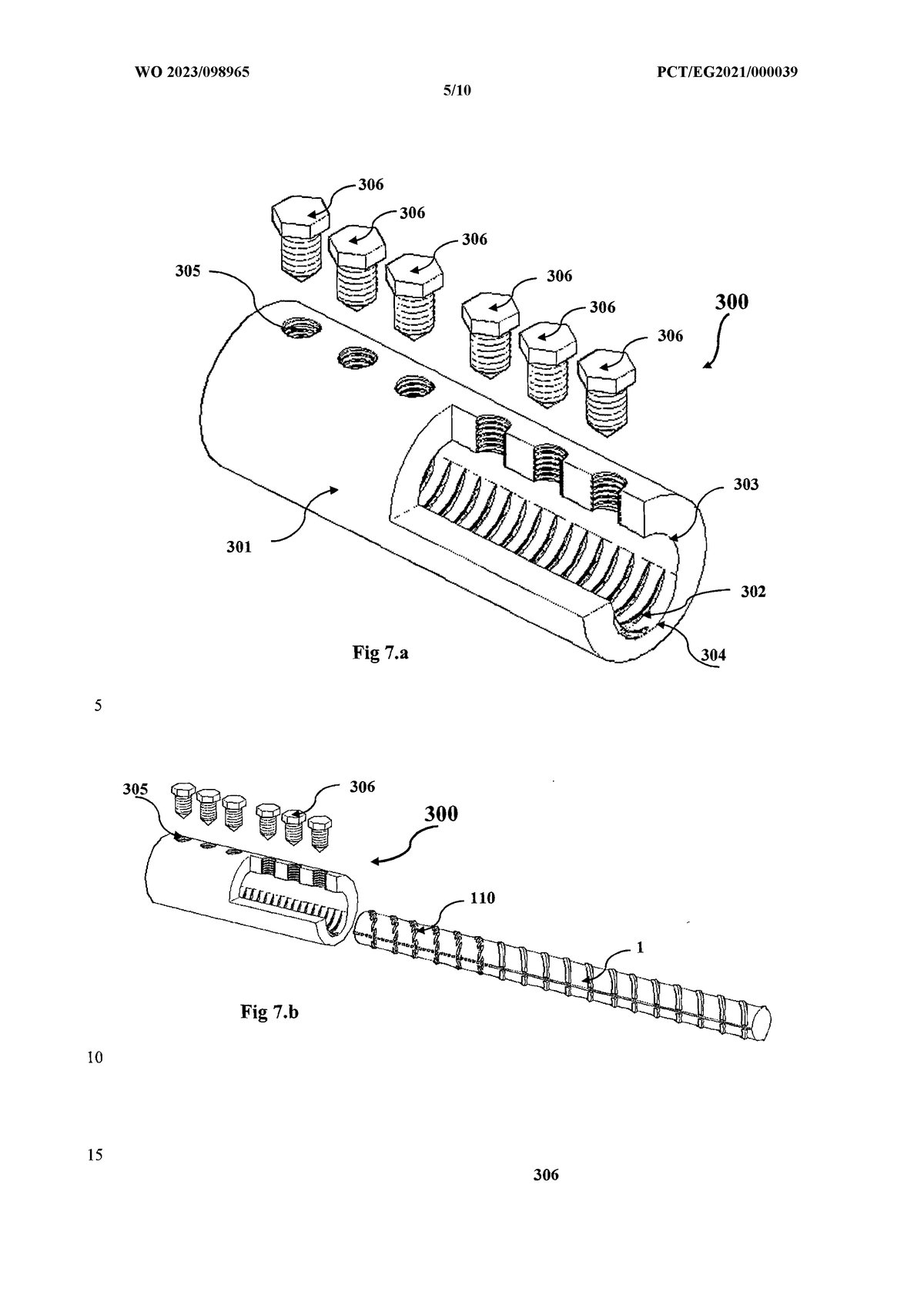
WO 2023/098965 A1 PCT/EG2021/000039

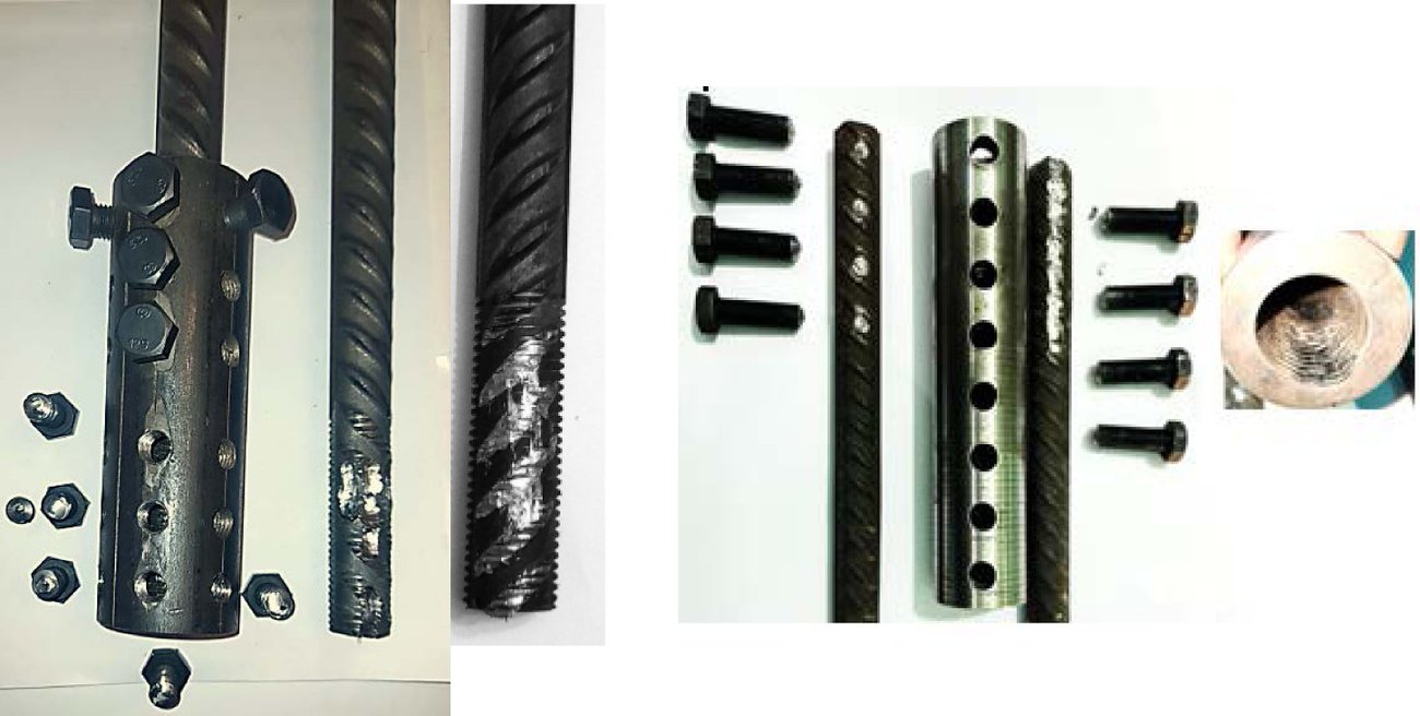
The coupler sleeve halves and screw elements, disassembled. Assembly drawing of the coupler: sleeve, threaded holes, threaded bolts and the two reinforcing bars.
Coupler sleeve, threaded bolts, and the male and female interlock with the bar ribs.

Three ways of closing it

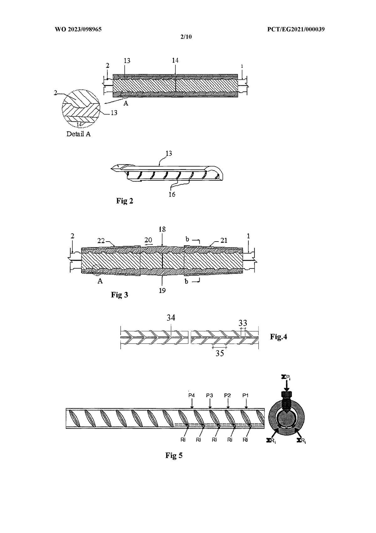
Patent drawing: coupler sleeve halves closed by an outer cylindrical pipe.
Closure 01

Outer cylindrical pipe

Two sleeve halves plus an outer pipe whose internal diameter is slightly less than the outside of the halves. The bar ends are seated in the female grooves, then the pipe is driven over the assembly — enough pressure to stop the two bars splitting apart.
Patent drawing: sleeve halves with an outward slope, closed by two tapered pipe locks.
Closure 02

Tapered pipe locks

The sleeve halves are given a gentle outward slope towards each end. Two tapered locks with the same internal slope are driven on from either side, closing the halves onto the bars.

Coupler halves with bolt holes, the screw elements, and the machined interlock with the bar ribs.
Closure 03

Bolted halves

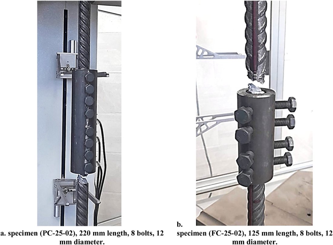
Two coupler halves with protruding sides and bolt holes. The bars are seated in the grooves and the threaded bolts on the protruding sides are tightened — the version that needs no press on site.

The parts, and the test

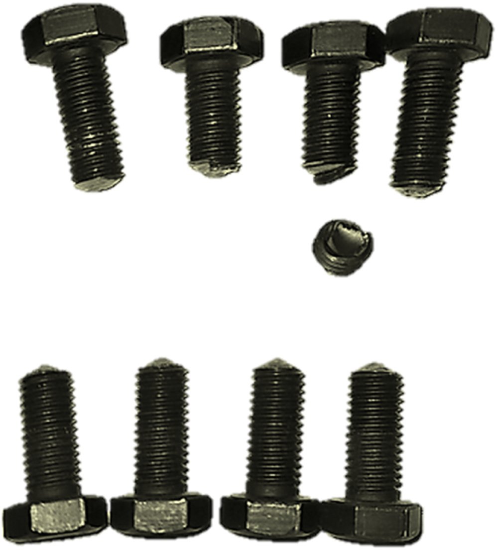
The screw elements: eight tightening bolts and one small filler screw.
Screw elements and the filler screw that closes the remaining space in the sleeve.
A coupled bar, a machined sleeve half showing the female grooves, and a complete coupler on a bar.
Female grooves machined to copy the bar ribs exactly — no clearance, no filling material.
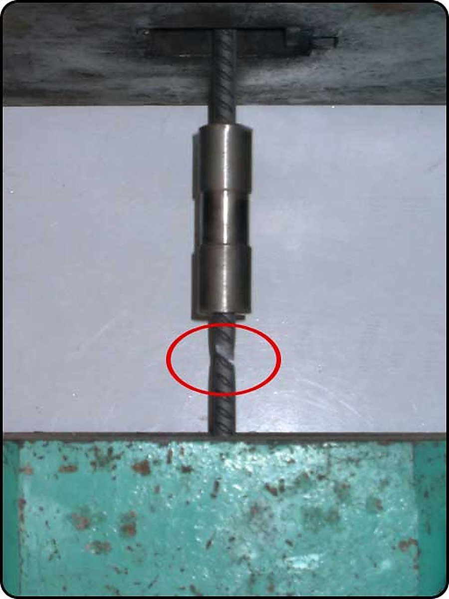
A coupler mounted on a bar in the testing machine, with the failure point on the bar circled below the sleeve.
In the machine: the bar necks and breaks below the sleeve, circled.
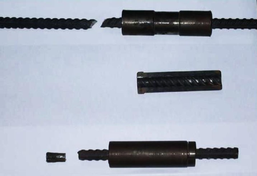
Tension test specimens: the reinforcing bars have ruptured outside the coupler, which is undamaged.
Sleeve half and two tested specimens: under tension the bars ruptured outside the coupler.

That is the only result a coupler needs to produce. If the bar fails away from the connection, the connection is stronger than the bar — and the designer can treat a coupled bar as continuous.

  • No threading, upsetting or grinding of the bar end
  • Short sleeve, small volume of steel per connection
  • Three closure methods to suit shop or site conditions
  • Also used as the joint element in the ACT truss systems

Patent record

Licensing, manufacture,
first application.

All five systems are available for licensing and joint development, including the laboratory programme needed to qualify them in a new market.

Talk to us